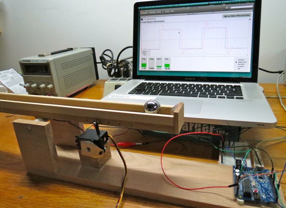
As an example of a lecture/showcase demo apparatus project, we show here the Furman Ball-on-Beam PID Controller. This device was assembled using fabrication techniques and construction philosophy borrowed from the Maker Movement.


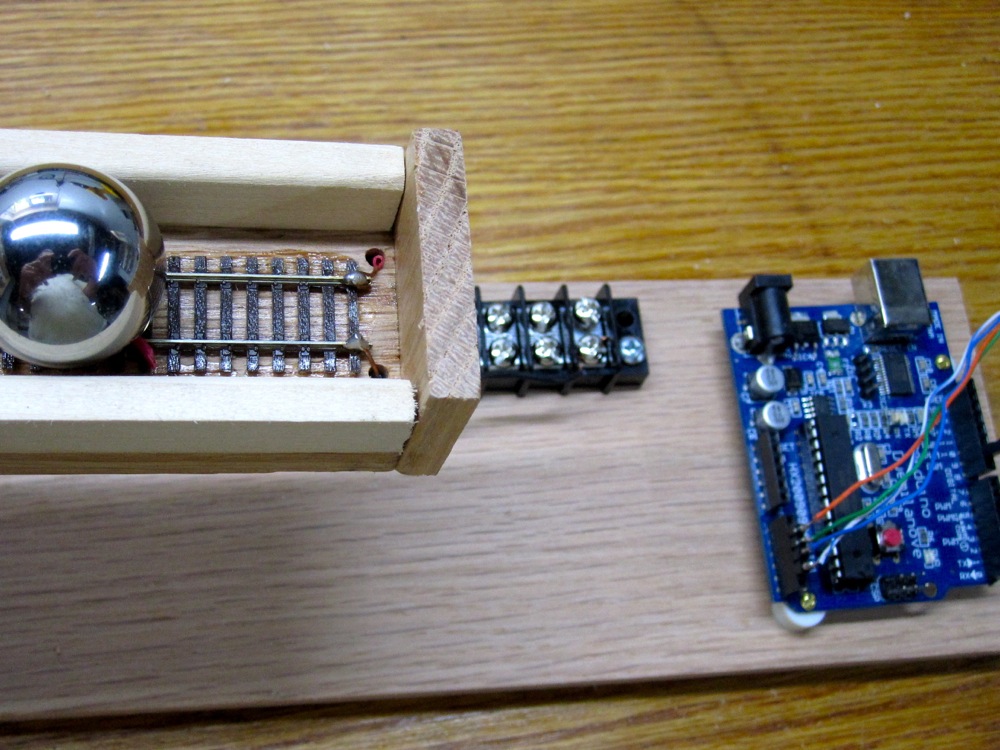
In the spirit of the Maker Movement, the need to have a machine shop fabricate an electrically isolated pair of rails with high mechanical precision was eliminated by re-purposing a length of N-gauge model railroad track. Mechanical supplies were restricted to those obtainable from Lowes and Home Depot. The Arduino was purchased at Radio Shack, and the railroad track and servo were purchased at a local hobby shop.
The objective of this project was to create a control system that could effectively balance a ball on a metal beam using a servomotor input to control the angle of the beam. The ball-on-beam balance problem is a classic open loop unstable system. For a constant input there is a non-constant output. A constant beam angle causes the ball to accelerate due to the force of gravity and the ball’s position increases non-linearly. The Arduino provides a closed-loop control system; a sensor monitors the system state (the ball position) and feeds the data to a controller that adjusts the beam angle as necessary to maintain the desired system setpoint. Utilizing this closed loop feedback, the controller is able to repeatedly and effectively balance the ball at the given desired reference point with reasonable transient performance. The P, I, and D parameters are chosen in the Arduino code to provide a feedback signal to the servomotor that depends on the error signal e(t):
e(t) = setpoint(t) – position(t),
where setpoint(t) is the desired position as a function of time, and position(t) is the measured position. With this input signal, the controller then calculates an output(t) to the servomotor given by:
output(t) = P e(t) + I ∫ e(t) dt + D d/dt{e(t)} ,
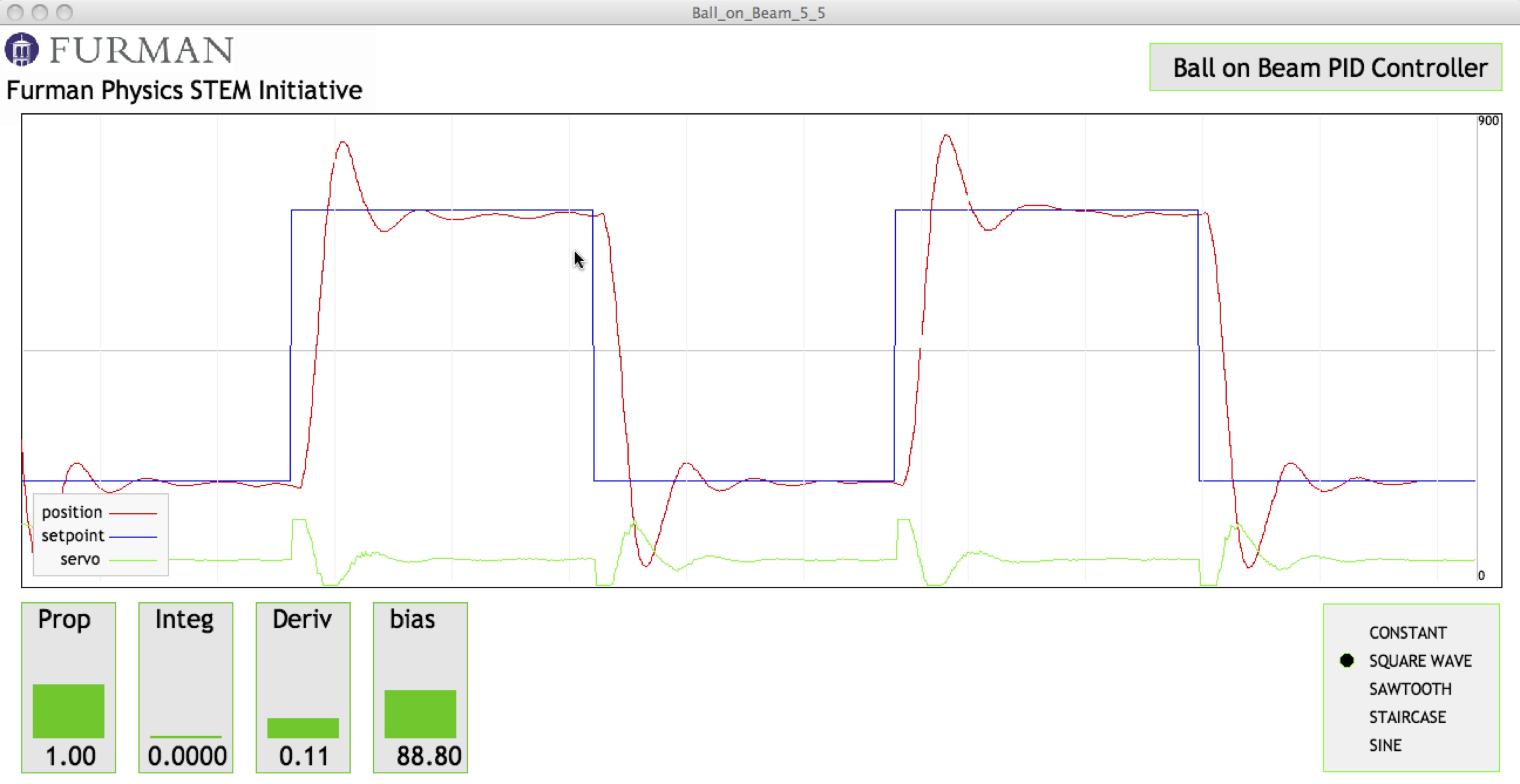
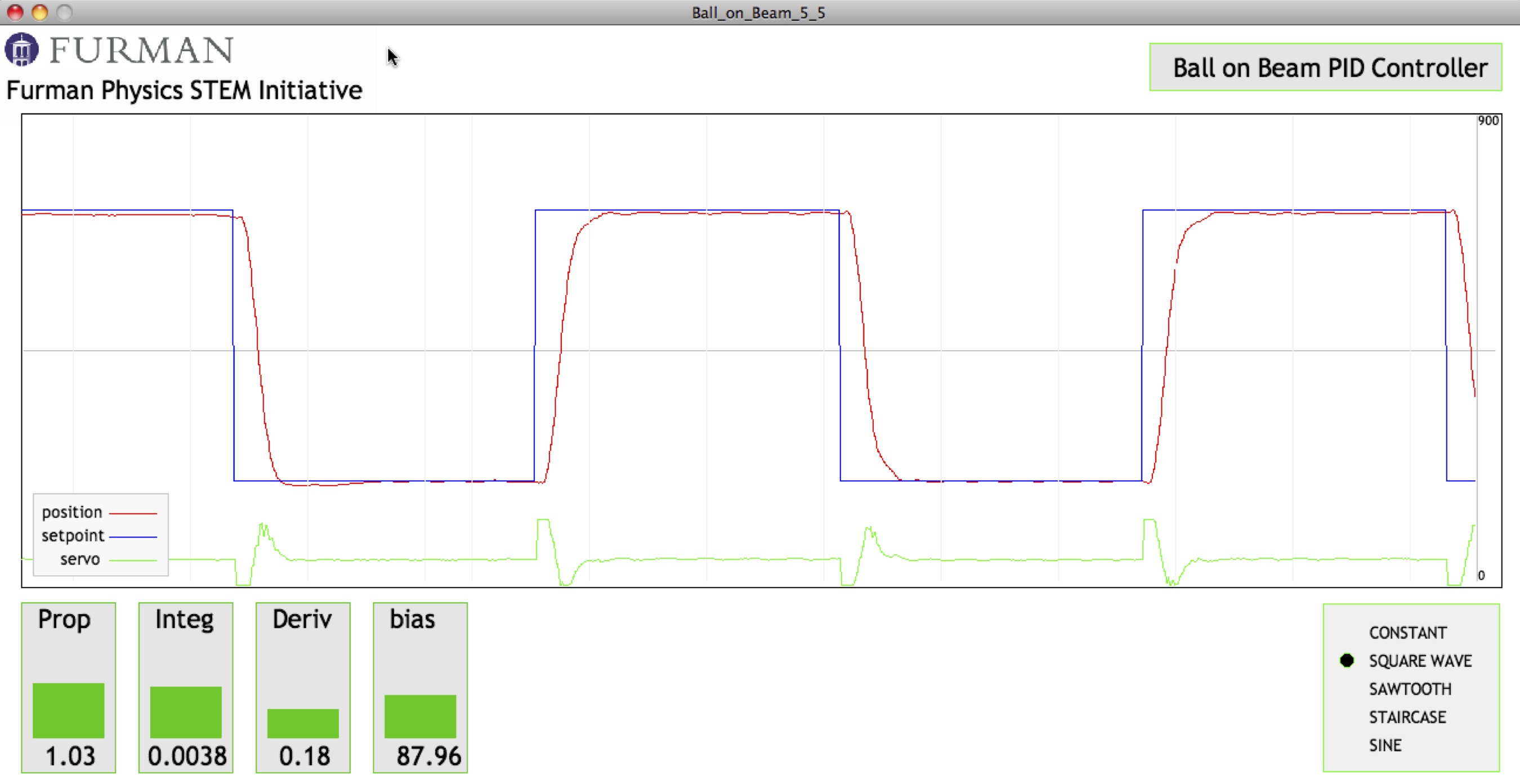
where P, I, and D are constants chosen in the Arduino code to provide an optimum feedback signal. The behavior of the system for non-optimized and optimized PID parameters is shown in below.


This apparatus serves as a very attractive model system for our students. In their first semester physics course, the ball-on-inclined-plane problem is a classic problem that students analyze in terms of a free body diagram, and then kinematic description. The sensor technology (digital/analog reading of the ball’s position from the potentiometric voltage divider provided by the ball and rail) is well understood by the students from their second semester physics course.
.
i need full document for this project
Hi, I like the idea of using a resistive rail to measure the position. Could you possibly go a little bit more into detail? What material is it? How heavy is the ball you are using? How does contact resistsnce affect you results?
I’m trying to replicate this project but the ball I use combined with constatan wire don’t result in good measurements. The resistance fluctuates heavilyand is of no use.
Thanks for any help in advance.
I’m a little bit confused about how you perform the ball position measurement. Could you please clarify a little bit more this point?
Many thanks in advance.
One rail of the railroad track serves as the resistor part of a potentiometer, and the ball serves as the wiper of the potentiometer–the wiper voyage is read on the other rail.
morning sir i would like to build and run this project but i just bought my arduino uno. i dont know much about c programing would you help me . im focusing now on modelling the system into mathematical equations
best regards
Morning sir thank you for this wonderful video. I would love to make this for my final year project in 2months time. But I never used arduino and don’t know how to program it. I’m process control student in a small country in central africa Gabon and I will order my arduino from south africa. Would u mind give code and line program explanation. Sorry for my english. Best Regards
Hi
excuse me sir! I appreciate you for share this project!
I need some help! I have to build ball and beam and I built it with mega32 and rc servo motor- but I don’t know how can I use pid output as a ocr1a value for pwm generation!
I use icr as a 50 hertz pulse generation and ocr1a as a pwm! but I don’t understand! when I use pid output as a pwm value on ocr1a rc motor goes end and it will stay there! timer vale is correct and it work without pid value fine but when I use pid and running that in while loop it is happening.
would you help me please as soon as possible?!
Andrew,
I am WAY BEHIND in doing what I had intended to do much earlier, which is to set up a Github repository for all the code on this site. I hope to get that task accomplished very soon. In the meantime, I might be able to help you if you could (1) post the fragment of your code that is causing a problem, and (2) a description of exactly what the problem is.